Vector Graphics
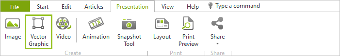
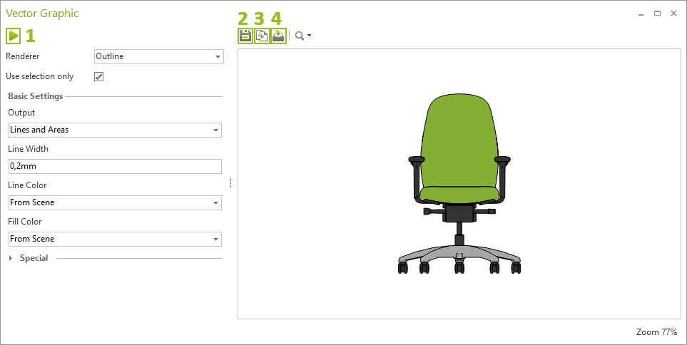
Click the Vector Graphic button, Presentation tab, to open the dialog for generating vector graphics. This dialog follows the Image dialog in its features: You edit image calculation methods, display settings and quality parameters. Then click the start icon (1) to calculate the vector graphic from your current planning view. The image appears in the preview area of the dialog. Export it by using the save icon (2).
The Vector Graphic dialog provides the following settings for calculating vectorized images:
Seting |
Background |
Renderer |
Determines the render mode for the vectorized graphic. Three options are available: |
Outline |
The lines and areas in the planning are rendered as vectors. If Outline is set as Renderer, the special settings become available. |
Wireframe |
Vector grafic is created in render mode Wireframe. |
Hidden Line |
Vector grafic is created in render mode Hidden Line. |
Use Selection only |
Creates vector graphic from the objects selected in the drawing. All other objects are automatically hidden. |
Basic Settings |
|
Output |
Available for Renderer: Outline. |
Lines |
All lines of the objects in the planning are generated as vectors and displayed in the Line Color selected. Areas are not computed. |
Lines and Areas |
Lines and areas will be rendered and displayed as vectors. |
Line Width |
Set with for the lines in the image in millimeter. |
Line Color |
Set color for the lines in the image. |
Fill Color |
Monochrome: Set one color for all areas in the image. From Scene: Texturated and multicolor areas will be displayed in a corresponding color average value. |
Available for Renderer: Output. |
|
Quality |
Determins image quality by number of scanlines. |
Scanlines |
The higher the value, the more individual lines the scene is split into for image processing. The more lines, the better the result and the slower the image processing. Maximum: 20000. |
Smoothing |
The higher the value, the more lines are combined into one line in the vector image. |
Min Line Length |
Removes all lines from the image that are shorter than the set threshold value (in pixels). |
Min Area Size |
Removes all areas from the image that are smaller than the set threshold value (in pixels). |
Exporting Vector Graphics
From pCon.planner 8.2, the export of vector graphics will take place directly from the Vector Graphic dialog. Exporting via the Start Menu is no longer required.
The following file formats are available:
•SVG
•DWG/DXF
•EMF
In addition, you can use the dialog to create the following standard image formats: JPG, PNG, BMP.
Copying vector graphics to clipboard
Use the Copy button (3) to copy your vector graphics to the clipboard. Then simply paste it directly into the workspace of the pCon.planner or into an external image processing, presentation or CAD program.
Insert Vector Graphic from Dialog into Drawing
Following a click on the Insert button (4) in the Vector Graphics dialog, your vector graphic is attached to the cursor and can directly be placed in the drawing.
Tips and tricks
•If you want to use a vector graphic as a true-to-scale 2D representation in your planning: Use a 2D view, orthographic view, or isometric projection as the basis for the vector graphic. Vector graphics based on perspective are not to scale.
•Important: The Contour mode cannot be used in Compatibility mode.