Drawing Walls
pCon.planner offers you two ways of creating rooms. You can put a room together from individual walls, or you can use the Rectangular Room tool to create a complete room instantly. Both of these methods are explained here.
First come some tips for presetting certain items such as Height and Depth or the Hatch Type to be used and then you are shown the options available to you while creating a wall or a room.
|
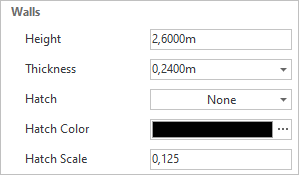
It is possible to set Height and Thickness for walls or rooms during the drawing process. First start the drawing procedure. Then, if you open the context menu with a right mouse click, you will find it has items for Height and Thickness, as well. |

Standard values for Thickness are provided and can be selected using the Context Menu. It is also possible to input a custom value. The most recently entered values will also be included in the selection. You can modify the wall dimensions once the walls are drawn by using the Properties dialog.
|
The options arrow within the Room Elements group will take you to the hatch settings for walls. Clicking on the arrow opens the relevant dialog. It is possible to enter not only the pattern. The scale is the distance between the lines shown in the Hatch, measured in meters. The hatching settings are pre-defined in this dialog for any walls to be created, but can also be altered retrospectively for each wall separately. There are more details on this here. |
Change Wall Starting Point and Endpoint
|
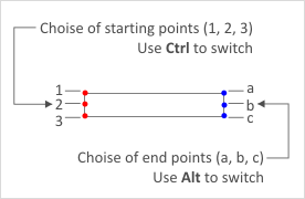
Having started to draw (see below) you can switch between three different sorts of starting and endpoints using the Ctrl and Alt keys. The following image shows a wall with its optional starting points in red and its optional endpoints in blue. The choice you make and the various combinations possible allow considerable flexibility in the creation of layouts. |
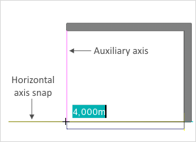
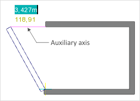
Besides the coordinate axes which become visible with Axis Snap, there are more auxiliary axes accessible while walls are being created. They will always become visible during drawing when the cursor cuts across one of four corner points of a wall which has already been created, either horizontally or vertically. The two images below show two auxiliary axes in red as well as the horizontal coordinate axis (left image) which has become visible.
By using the coordinate axes and auxiliary axes the orientation of walls can be optimized during the drawing procedure.
|
|
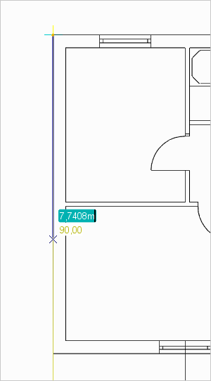
The best projection for drawing walls is Top. Individual walls are drawn in order to create individual rooms.
|
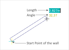
1.Click on the Wall icon in the Room Elements group, Start tab. 2.Now click in the viewport to set the start point for the first wall. 3.Now set the angle and length either by moving the mouse or entering the figures on the keyboard. 4.Another click or pressing the Enter key when the values for length and angle have been typed will fix the wall. |
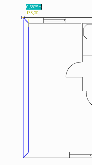
This drawing operation can be repeated as often as you like. The end of the wall just completed will always be the start point of the next wall.
If you are drawing walls and click when the endpoint of the current one touches another wall, the drawing operation will be concluded. Each drawing operation can be aborted by pressing Esc or selecting the Cancel item from the context menu.
As well as creating rooms by drawing individual walls, you can create whole rectangular rooms instantly.
|
1.The best projection for this is Top. 2.Click on the arrow circled in green (Room Elements group, Start tab) as shown on the left and select the Rectangle Room item from the drop-down menu which opens. |
|
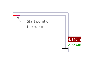
3.Click somewhere in the viewport to fix the starting point of the room (see screenshot on left). 4.By pressing Ctrl you can affect whether the origin of the room is in the inside corner, the outside corner or centered in the wall. 5.By moving the cursor or entering figures you can change the length and breadth of the room. 6.This is again fixed by a mouse click or by pressing Enter. |

Note: On our Youtube channel you will find a video on this topic |
||
|
|
This video shows you the basics functions of using floor plans in pCon.planner. You will learn how to import, scale and crop PDF floor plans correctly. |
In pCon.planner, you can import floor plans in PDF format and trace them using the Floor Plan tool.
The import works as follows:
1.Click on File to open the Application Menu.
2.Select Import and choose PDF Document (*.pdf) from the list of supported formats.
3.Choose a floor plan in PDF format from your local file system that you would like to import.
4.Click Open.
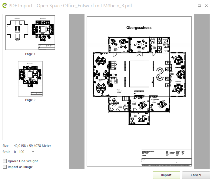
5.The PDF Import dialog will then open. It will include the following options:
▪Select Page
▪Scale (use scale from PDF)
▪Ignore Line Weight
▪Import as Image (recommended for low-quality PDFs)
▪Insert Text as geometry
▪Stack Elements (hamburger menu at the bottom left of the dialog, used to keep the stacking of elements in the PDF or – if deactivated – to set all elements in the PDF to zero level)
▪Zoom on the preview image (per context menu or STRG+mousewheel) or move it (click on mouse and move cursor)
6.Determine your settings in the dialog and then click Import.
7.The PDF page will be attached to your cursor and can be placed within your plan.
Modify PDF Floor Plan
The floor plan will be in the plan as a Group. By double clicking, you can move, edit or delete individual elements from the group.
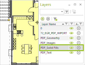
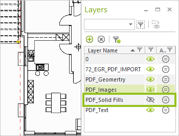
Control Floor Plan Display
With the Layers dialog, you can control which content from the floor plan is shown: Background images, texts, and hatchings can be shown or hidden.
|
|
Trace Using the Floor Plan Tool
Note: On our Youtube channel you will find a video on this topic |
||
|
|
The floor plan is imported, scaled and cut - now comes the tracing. In this video, we'll show you a few tricks you should keep in mind when redrawing floor plans in pCon.planner. We answer the question of how to tap the correct wall thickness and how to connect and divide walls. |
|
The Floor Plan tool can be found under the Start tab in the Room Elements group. With this tool, you can trace a wall from the floor plan and pCon.planner will automatically generate 3D walls.
|
|
1.The best projection for this is Top 2.Click on the arrow circled in green (Room Elements group, Start tab) as shown on the left. Select the Floor plan item from the drop-down menu which opens. 3.Click on a point within the workspace where you would like to draw the wall. In the example, this is the corner point of a wall from an imported floor plan. 4.Trace the outline of the wall with the Floor Plan tool. 5.The drawing process ends once you have reached the starting point again. A wall will automatically be generated. 6.Repeat the process for each wall within the floor plan. |
|
Note: You can add windows and doors to the wall as usual. Use the Wireframe render mode to place the room elements at their desired positions. To create a further wall outline, press F2. |
|
|