Inserting and Editing Objects
You can insert various objects into your Layout pages. In this chapter you will learn how to insert viewports and stamps and how they can then be edited using the Properties editor.
Other options available in the Layout area are the insertion of images and drawing elements.
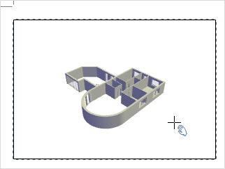
Using the Viewport means that views of the design area can be placed into the Layout area. This is how:
|
1.Click on the Viewport button in the Tools group, on the Layout tab. 2.Now click anywhere on the page and drag to create the Viewport. 3.A second click will fix the size of the window. 4.It is now possible to create further viewports on the Layout page. The Properties Editor and Interaction mode allow the user to make individual settings for each Viewport. |
Editing Appearance of Viewports
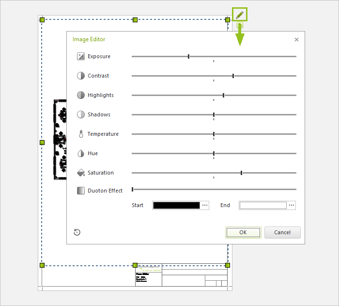
The Image Editor is available for viewports. You use it to edit the appearance of viewports in the same way as the contents of screens in the planning area.
1.Select the viewport that you want to edit.
2.Click the green pencil at the top right of the viewport to open the Image Editor.
3.Make your settings for exposure, contrast, hue, etc. in the Image Editor. The effects are directly visible in the viewport.
4.Confirm with OK.
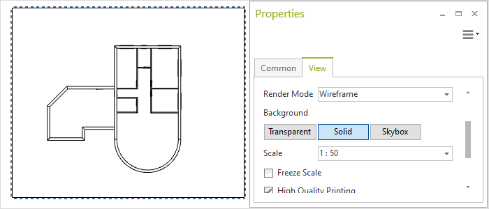
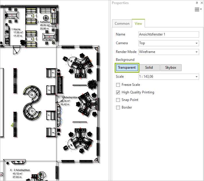
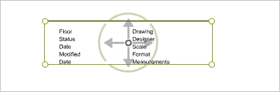
The properties of any object on a Layout page can be edited separately. For this, the Properties Editor is an important tool, to be found on the Toolbar within the Layout area. Select any object on the page, then click on the Properties button. Now you can start to modify them. The following screenshot shows the properties of a Viewport and the modifications that can be made to it.
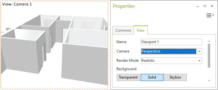
The Camera item is where all standard projections a Camera defined specially for the design can be selected. The Render mode or Render style can also be set for each Viewport, a Title given to it or the Border color set, etc.
A scale can be defined for viewports in isometric projection as well for a viewport in a 2D view. Under the Properties Editor, use the Camera entry to set the view to one of the aforementioned projections. Under Properties Editor you can than set predefined standards in the Scale field, or you can enter your own values.
Disable vector printing to print in conventional quality. This way, the file size of the PDF will remain smaller and printing will save memory.
1.Open Print Preview or your Layout area.
2.Click on the viewport for which you want to disable enhanced line printing.
3.Find High Quality Printing in the Properties Editor.
4.Remove the checkmark from this option.
Note: If High Quality Printing is active, you can additionally check the option Print Simplified Edges. This option ensures faster and more compact printing and therefor leads to smaller PDF files that load quicker. This option can lead to loss of details.
The Shadow option – Tab Common in the Properties Editor - sets a shadow cast for the viewport or other objects on your Layout page. This setting interacts with the viewport background settings (tab View in the Properties Editor):
•If a Shadow is set and Background: Solid is specified, the edges of the viewport will have a shadow cast.
•If a Shadow is set and the Background is set to Transparent, the lines in the viewport will get a shadow.
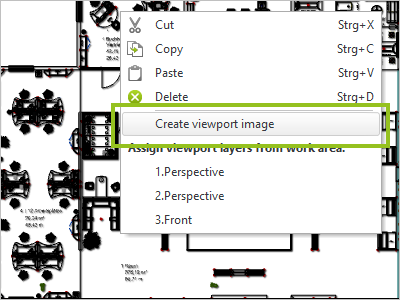
You can insert multiple images from a preset viewport directly into your layout.
1.Create and edit your viewport. 2.Select the viewport. 3.Open the context menu with a right click on the mouse. 4.Select the option Create viewport image. 5.A high-resolution image of the viewport is generated and directly inserted in the layout. 6.Position the image as desired. |
|
Note: If necessary, delete the underlying viewport. If you insert images into your layout instead of the original viewport, you can improve the performace for large layout pages. |
|---|
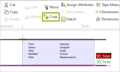
Crop PDF floor plans and stamps on your layout pages using the Crop feature. This works in the same way as the 2D Crop feature in the planning area.
1.Select the floor plan or stamp on your layout page that you want to edit. 2.Start Crop (Layout tab, Tools group). 3.Click the desired point on the PDF floor plan or stamp and draw a selection area around the area you want to keep. Alternatively, click the starting point of the selection and enter the desired size using the appropriate values. 4.Confirm with a click on the left mouse button or press Enter. The selected area of the floor plan or stamp is retained, the rest is deleted. |
|
|
In the Tools group, you can find options for inserting dimensions into your layout page. You can add simple, rotated, angle, radius, diameter and circular arc dimensions in the layout area. In the Insert group, you can also find Callouts (Text menu). More information on inserting dimensions can be found here.
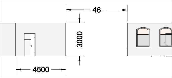
You can dimension viewport content as well as distances between viewports and further objects on your layout page. What’s important here is:
•If you are dimensioning within a viewport, the dimension line will automatically attach to the lines and edges in the viewport. Dimensions within the viewports reflect the dimensions of the contained objects in the planning area. The attachment of the line to the viewport content will occur regardless of whether you started the interaction mode or set a measurement in an inactive viewport.
•Dimensions between viewports, drawing elements etc. on the layout page specify the distances on the print page. These dimensions will indicate the lengths and sizes that the depicted objects on the print page had.
Example:
Note: To distinguish between the two dimension levels, pCon.planner will give you a warning if you are not above a viewport before you set the extension line or dimension arrow.
Please only use dimensions in windows where you have enabled the Freeze Scale option (Properties Editor), otherwise zoom movements in the viewport may lead to unintentional changes in dimensional orientation.
Using Dimension Styles
The dialog Dimension Styles is also available in the layout area. Please create your own dimension style for your layout page. The size of the dimensions and other properties are oriented to the size of the layout page so that the proportions from dimension styles in the planning area do not match to the scale of the print page. If you use a dimension style from the planning area, dimensions or arrows may appear too large in relation to the content of the output window.
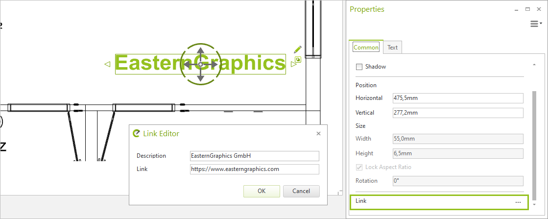
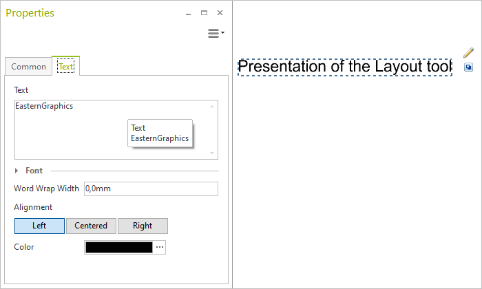
In the case of text, editing can be done not only in the Properties Editor but also with the pencil symbol, which becomes visible when the text is selected (see screenshot below).
You can place links to web pages or external documents at any element (e.g. texts, viewports, images...) on your Layout pages:
1.Select object on the page
2.Property editor, switch to Common tab: Click on ![]() at the right edge of the Link line.
at the right edge of the Link line.
3.The Link Editor opens. Enter the desired link for the object as well as a description if necessary and confirm with OK.
The link can now be viewed in the property editor as soon as the object is selected. Furthermore, the link is integrated as an interactive element when you create a PDF from your layout page.