Render
Note: On our Youtube channel you will find a video on this topic |
||
|
|
Depending on the planning stage and the visual requirements to the design, switching between the different render modes is necessary. Starting with the floor plan and ending with a realistic rendering, the render modes enable a step-by-step approach to the final result. In this video we show you the 6 different render modes and what benefits they have! |

It is possible to assign to any viewport in pCon.planner not only an individual Projection but individual rendering. There are a number of settings available in the program and these are now explained.
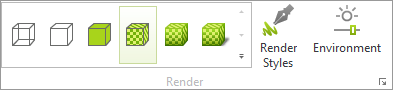
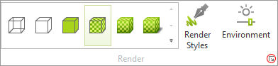
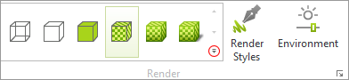
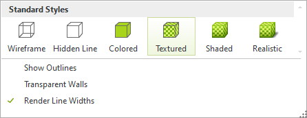
Every viewport can be given its own rendering. The various options are to be found in the Render group, View tab. As an alternative, access the render modes from the Render dropdown menu in the Viewport control area. |
|
Wireframe
|
The Wireframe mode models all the objects in the current plan as a wireframe. Only the construction lines of the elements are shown. As surfaces are not visualized here, access to objects in Wireframe mode (for example, in order to move them) must always be carried out using the visible lines. |
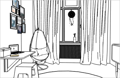
Hidden Line
|
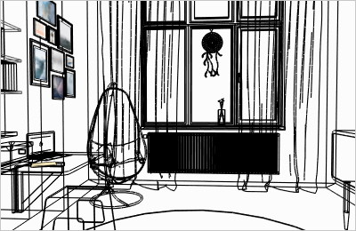
In the Hidden Line mode only the edges which are in sight for the observer are shown. The areas between the lines are filled in as white. In Hidden Line mode, objects can be selected both from their visible edges and from their surfaces and then edited. |
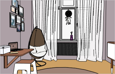
Colored
|
In the Colored render mode, objects with edges and colored surfaces will be shown. As opposed to textures and multi-colored materials, this mode will display a corresponding color value. This mode frees the system resources from having to calculate light and shadows.
|
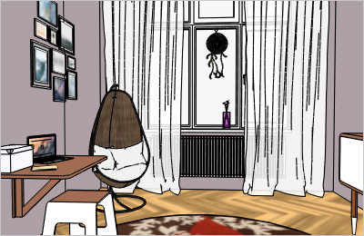
Textured
|
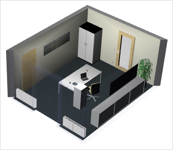
The Textured mode renders not only the edges but also colors and textures of objects. However, this mode saves system resources by doing without any calculation of light and shadow. |
|
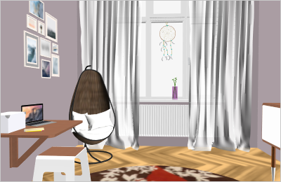
The Shaded mode, unlike the modes so far mentioned, will, when rendering objects, take account of light sources in the plan as a whole. It differs from Realistic mode in using a simplified light model, which leaves out calculations of shadows, for instance. It gives a speed advantage in the calculation of the current rendering. |
|
Realistic render mode reproduces textures and colors in the highest quality. Lighting and shadows will also be simulated: The Realistic mode works with ambient occlusion. The resulting lighting effect corresponds to the interaction of light and shadows on a cloudy day. In this mode, self-luminous and glossy surfaces will be displayed with a light aura (blooming). |
Note: With the Ambient Light function, in the dialog Environment (View tab, Render group), you can set the global background lighting for your plan. This background lighting affects the display in both Shaded and Realistic render modes.
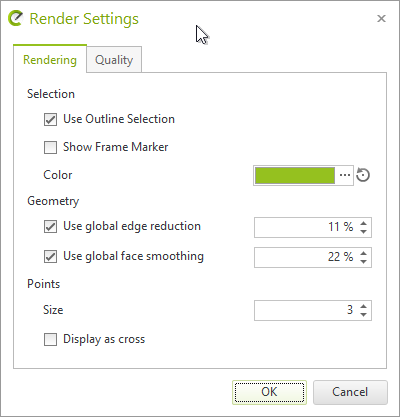
To open the Extended Options, click on the arrow symbol highlighted in the image on the right with a red circle. |
|
Rendering tab
|
Use Outline Selection Edges of selected objects will be marked if this option is activated. Color is used to define an individual color for your marked outlines. Show Frame Marker for Multi Selection If this option is active, a bounding box will be displayed in addition to the marked edges in case of multi selection. Use global edge reduction Depending on how they are constructed, objects will have a varying number of edges. It is advisable to check this item to improve rendering. |
Points
The Point Size in pixels sets how big the points (including insertion points for objects) will appear in the display.
You can also use a check mark here to specify whether these points are to be displayed as crosses. This increases the visibility of points.
Use global face smoothing
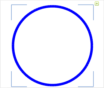
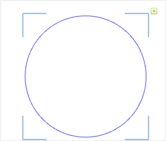
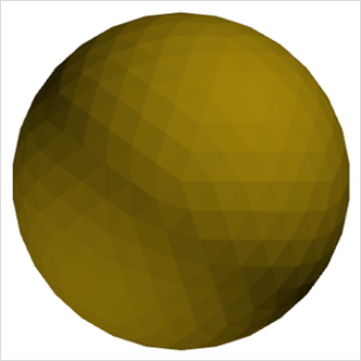
Objects made up of meshed surfaces can be smoothed by any selected percentage to make them appear more real. The difference is clear from the next two screenshots: The illustration on the left shows how the sphere (made up of polygons) is rendered using 0% global face smoothing. The right hand illustration shows the same object with 20% global face smoothing.
|
|

Global face smoothing can also be applied to individual objects. More on this is to be found here.
|
Quality The higher the quality setting for Texture, Shadow and Anti-aliasing, the better they will appear in real-time rendering. However, such improved quality levels will also require more graphics memory. Antialiasing determines how smooth the edges of an object in the plan are displayed. Smoother edges appear more harmonious. Performance Use Quick Rendering is active by default. In the Realistic render mode, it improves navigation and performance in complex drawings. If Quick Rendering is activated, pCon.planner switches of ambient occlusion in complex drawings during navigation. |
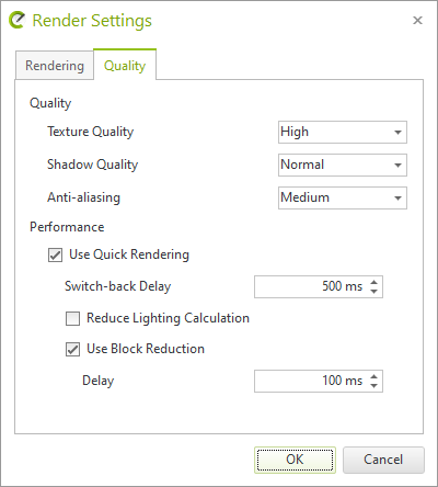
Reduce Lighting Calculation is used to deactivate additional light sources during the navigation process. Use Block Reduction causes a switch from the active render mode to a simplified display mode during navigation. The switch-back is done automatically after the navigation process.
Switch-back Delay determines when to switch back to the original render mode following calculation.
|
In Shaded and Realistic modes, the highlighting of Outlines is disabled by default. By enabling the Outlines item, which is shown by clicking on the icon circled in red in the graphic on the right, you will activate highlighting of Outlines in these modes. |
|
|
To compare the appearance of enabled and disabled Outlines, see the two following graphics. |
|

|
|
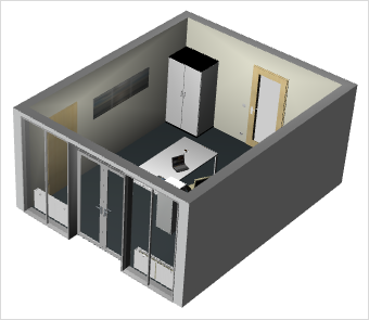
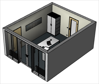
Besides Outlines, there is another rendering option: Transparent Walls. Enabling this item means that walls and ceilings which previously obstructed the view into the plan will appear as transparent. There is a comparison in the next two screenshots. |
|
The left-hand image is without, and the right-hand image with Transparent Walls.
|
|
There is an additional rendering option known as Render Line Widths available for working with Drawing elements. When this is enabled, the line width set in the design for drawing elements which have no filling will be displayed. |
|

In the two following images, you can see the difference between rendered line width and non-rendered line width for the same object, on the left and the right respectively.
|
|