Projection
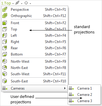
The angle of view onto your design can be set separately for every viewport. Within your current viewport, click on the text in the upper left corner and select a projection from the menu there. This projection will then be applied. Besides the standard projections, custom projections can also be created. These are known as Cameras. In addition, this is where you find the options for the creation of Clippings. |
The names used for the various projections are all derived from the view from above (Top). This relation works for all projections with the exception of Perspective view.
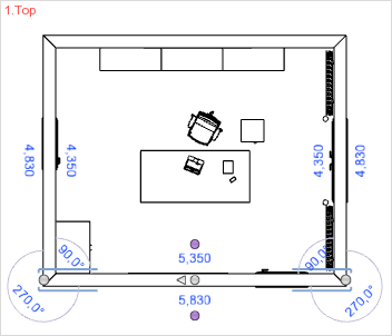
Top and Bottom The Top and Bottom projections are most useful when walls are being created or furnishings and equipment being added. They give a good view of distribution over the design, and figures for width and depth can be typed in. This is, for example, important while drawing walls. |
|
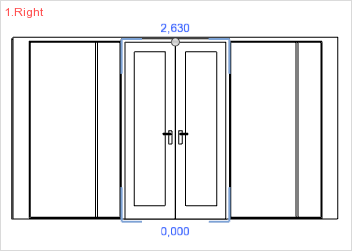
Front, Rear, Left, Right The Left, Right, Front and Rear views are suitable for editing objects found at these sides. By choosing the best view, it is easy to change the dimensions or positions of your objects. These options are particularly good for entering heights and distances for the objects. |
|
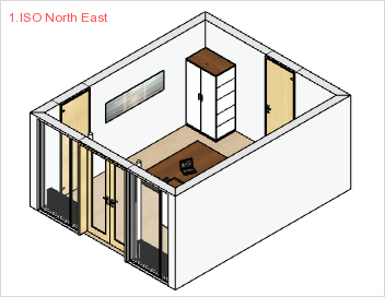
The South-East, South-West, North-East and North-West isometric projections are a way of visualizing in three dimensions without taking account of the natural distortion of perspective for the objects. They make the plan very transparent to the observer and it is easy to edit furnishings and equipment with them. |
|
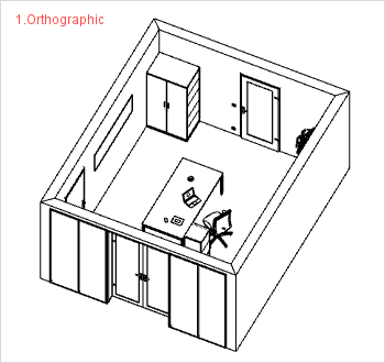
When the designer changes from a 2D projection such as Top into Orthographic projection, there is at first no apparent alteration in the image, except for the change in label for the Viewport. But when it comes to the navigation, the differences will be clear: In the projections described above (Top, Front, ISO etc), it is not possible to move freely using the Orbit function. The projections permit only the use of Pan and Zoom for navigation. In the case of Orthographic (or orthogonal) projection, all vertical edges are represented (rendered) as vertical and all edges that are parallel to each other are rendered as parallel. This removes the distortion which is typical of Perspective as a view.
|
|
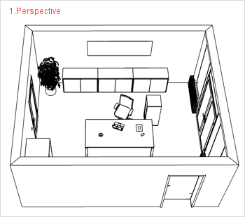
Setting Perspective will mean objects are represented realistically. This is achieved by taking account of the distortion of objects when seen in perspective. All the navigation options will be available within the Perspective projection: Pan, Orbit, Zoom, Look Around, Walk. If you create your own cameras, these will always be based on Perspective projection (see below). It is not possible to use your own cameras to create parallel projections per se.
|
|
It is possible for you to use projections other than those preset, and for this you need to create your own. These are known as cameras.
There are two ways of creating cameras.
Fixing the current view of the design
1.First activate Perspective in the current Viewport. 2.Then use the navigation tools provided to obtain the desired viewing angle. 3.Now click on Camera from View (View tab/Camera group). |
Fixing a view
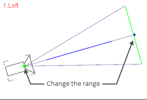
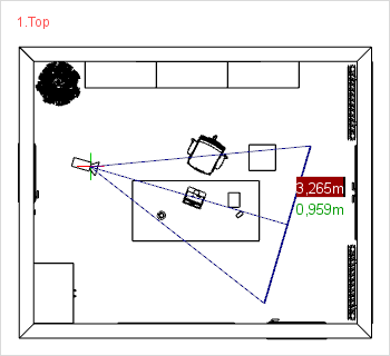
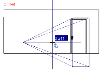
1.Choose a projection in which you wish to create the camera. The use of 2D projections is recommended as this makes exact positioning easier. 2.Click on the Camera button in the Camera group, View tab. 3.Now move the cursor to the position within your Viewport at which the camera (i.e. viewing angle) is to be created. A single click will fix the camera in the Viewport. 4.Now move the mouse within the viewport to decide the direction and range of the camera. You will see the changed values along the axes shown in the projection in relation to the camera’s position (see illustration on right). The values shown in the top-right screenshot are for the red and green axes. 5.A further mouse click will fix this range and the angle for the camera. It is also possible to type the values as an alternative method. 6.Depending on the projection you started with, it may be necessary to make corrections to certain axis directions as work proceeds. For example, the height of the camera is being adjusted in the lower right screenshot (see here also).
|
|
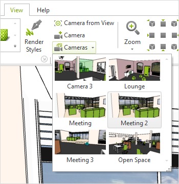
Any cameras you have created will be stored in number order. This means the first one will be called Camera 1, the fifth one Camera 5 and so on. The viewport control allows you to assign cameras to any Viewport. There is also the option of clicking on the arrow below the Cameras button in the Ribbon and selecting as desired, see the shot on the right. Hide and unhide Camera symbols You can display or hide camera symbols in your design by using the Layer dialog or, as appropriate, the Layer filter. |
|
The Cameras you have created have a variety of editable properties. To edit, you can go into the Properties Editor or you can employ a variety of interactors which are available on the geometric lines issuing from the camera. Either way, it is first necessary to select the camera to be edited. To open the Properties Editor, press F12 or click on the Properties button (Toolbar).
The following table gives the summary of the properties and the ways of modifying Cameras.
Properties |
Description |
Visualization |
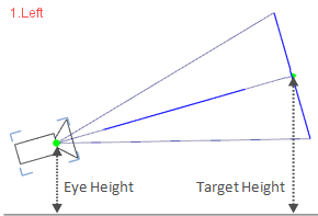
Eye Height |
This is the height of the camera “origin”. It can be altered from the Properties Editor or by interactor. |
|
Target Height |
This is the height of the target “origin”. It, too, can be altered from the Properties Editor or by interactor. |
|
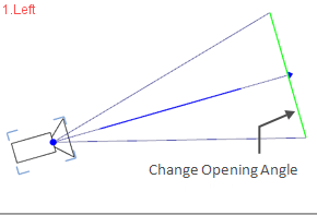
Opening Angle |
The opening angle influences the size of the range. It may be any value between 5° and 100°. Alterations are made from the Property Editor or the line indicated in the screenshot on the right. |
|
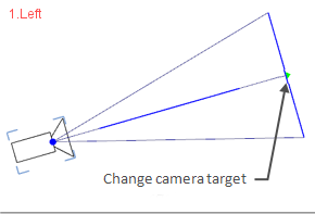
Depth of Field (can only be shown in photorealistic images) |
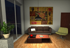
Depth of focus (Properties edtor) is the term used to describe the clarity of focus in a specific area of an image. Certain objects will be clear in the photograph, but what is in front of or behind them will be out of focus. If this option has been disabled (default case), all areas in the photorealistic image will be rendered with full clarity (see graphic on right). |
|
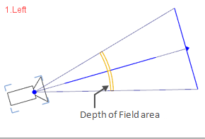
Depth of Field/ Distance (can only be shown in photorealistic images) |
If the option is enabled, it is possible to set the depth of focus either by entering a distance or using the interactive tool. In the latter case, select the right geometry for the camera by moving the yellow area (see graphic on right). |
|
Depth of Field/ Percentage (can only be shown in photorealistic images) |
The degree of clarity of the image can be set as a percentage in the Properties Editor. The higher the value, the clearer the picture and the lower, the fuzzier. The screenshot on the right is also to be found in higher resolution in the Single Frame section. |
|
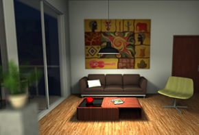
Changing camera position |
To move the camera around, use either the central line leading to the target interactor or use the geometrical lines appearing with the camera. |
|
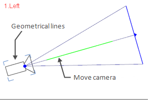
Changing camera origin position |
To move the origin of the camera around, use the interactor highlighted in the screenshot on the right. |
|
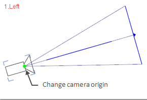
Changing camera target |
To move the target for the camera around, use the interactor highlighted in the screenshot on the right. |
|
Reducing or enlarging range |
One way of changing the range is to move the camera origin (by its interactor) and another is to change the opening angle. |
|