Drawing Elements
As the differences in the creation and editing of these elements lie only in the details, the procedures for drawing and editing polylines are given as an example.
This chapter concludes with a paragraph on the use of Line Styles. The following sections refer to the various 2D and 3D drawing elements in pCon.planner.
The following is a description of how to create a polyline:
|
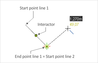
1.In the Drawing Elements group, under the Start tab, click on the button showing a line. 2.Go into the viewport and click to establish the start point for the polyline. 3.Using either keyboard or the mouse, the length of the line as well as the angle can now be set. 4.A second click will fix the end of the first line. The end of one line is at the same time the start of the succeeding line. Clicking on the endpoint, using the Finish item in the context menu, or pressing Esc will finish the drawing at that point. |
During the drawing process, guides to help with the parallel or orthogonal alignment of the lines will appear. When adding additional lines to a Polyline, snapping on segments and corners is activated automatically. |
|
|
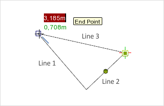
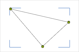
If the drawing procedure is not actively ended, it will continue until the mouse coincides with the end of a line. This principle is shown in the left-hand screenshot. Here, line 3 hits the end of line 1 (see also Tool tip). The drawing procedure would be ended with a click. The outcome would be a finished triangle. |
|
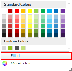
If polylines are to be closed or other closed objects such as a circle or cuboid are to be drawn, it is possible to set a filling for them before they are created. To do this, open the Color menu, Drawing Elements group, and activate Filled, the button highlighted in red in the left-hand screenshot. The Color of the filling can be set by the use of this menu, as well. A Polyline created without filling can later be converted to an area using the Region tool. Individual Filling for polylines and all additional closed drawing elements can be controlled using the Properties Editor. Here you can find various fill and shading options to choose from. |
When a drawing element has been created it can always be edited later. The possibilities are here shown for a Polyline.
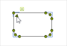
In the triangle, clicking on one of the sides will first highlight the whole object, as shown in the lower screenshot on the left. Now, to change the shape of the triangle there are two possible ways to proceed. Either click on the edit symbol (![]() ) or double-click on the object. The representation will then change to look like that in the right-hand screenshot.
) or double-click on the object. The representation will then change to look like that in the right-hand screenshot.
|
|
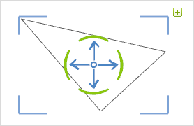
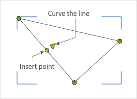
Clicking on the green interactor and then dragging will enable you to alter the shape of the triangle. If you move the mouse onto one of the sides of the triangle, further interactors will become visible (see left-hand screenshot below).
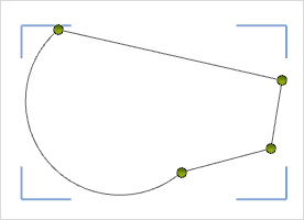
The triangular interactor (![]() ) enables you to introduce curvature into the lines. Using the rectangular interactor (
) enables you to introduce curvature into the lines. Using the rectangular interactor (![]() ) means that an extra point can be inserted between two line ends. The lower screenshot on the right shows two modifications of the original triangle. Both curvature and an additional point have been introduced.
) means that an extra point can be inserted between two line ends. The lower screenshot on the right shows two modifications of the original triangle. Both curvature and an additional point have been introduced.
|
|
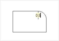
with the help of edge interactors, the edges of polygons, rectangles and multiple lines can be rounded. The triangular edge interactors appear when hovering the mouse over a corner. Once you click on the interactor, the edge can be adjusted and rounded by moving the mouse or by inserting a radius and pressing Enter.
The radius canalso be assigned to the other edges: to do so, hover the mouse over the next corner and click the triangular interactor. The radius is assigned. Repeat for all the edges. If you want to give an edge a different radius, click on the triangular interactor and hold down the left mouse button. You can then enter a new radius or drag the radius to the desired size.
|
|
|
The extrusion function enables two-dimensional shapes to be changed into 3D objects. The procedure is given here.
Multiselection for drawing elements
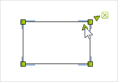
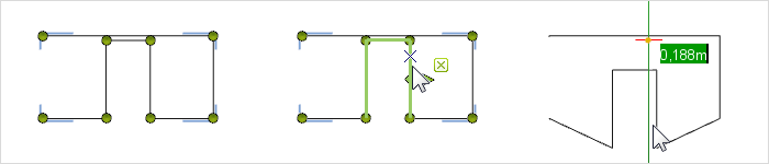
For two-dimensional drawing elements, several line segments or corner points can be selected at once.
After clicking on the edit icon (![]() ) , hold down the Ctrl key and select the desired elements with your mouse. The selected lines or corner points can then be moved together. What's great about this approach is that the length of the selected lines and their angles remain the same, whereas all other lines and points adapt to remain connected to the moved items.
) , hold down the Ctrl key and select the desired elements with your mouse. The selected lines or corner points can then be moved together. What's great about this approach is that the length of the selected lines and their angles remain the same, whereas all other lines and points adapt to remain connected to the moved items.
|
For drawing elements and for complete lines, it is possible to define a line style using the Properties editor. This line style will then be taken account of in printing, in real-time rendering, and in the creation of single frames. These functions are also available in the Layout area. The following table gives an overview of the editing options for line styles. |
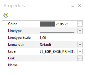
Drawing elements properties |
Description |
Line type |
Selection of predefined linetypes (e.g. broken) |
Line type factor |
Definition of the size and distances between the segments of the linetype |
Line width |
Width of the line |